When evaluating any line/network echo canceller using a laboratory setup, relevant echo path models connecting Rout to Sin are required. ITU-T G.168-2015 (and earlier versions) defines two groups of echo path models for evaluation.
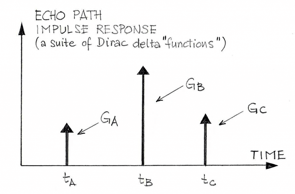
The first group comes from a very early version of the standard and these models are essentially in the form of three Dirac delta functions spread over time segments whose length is smaller than the echo coverage capacity of the echo canceller under evaluation. The motivation for creating such simplified models was to provide a coarse approximation of the multi-reflective nature of the echo path. By definition the dispersion of individual reflections is zero (analog view) or one (digital view).

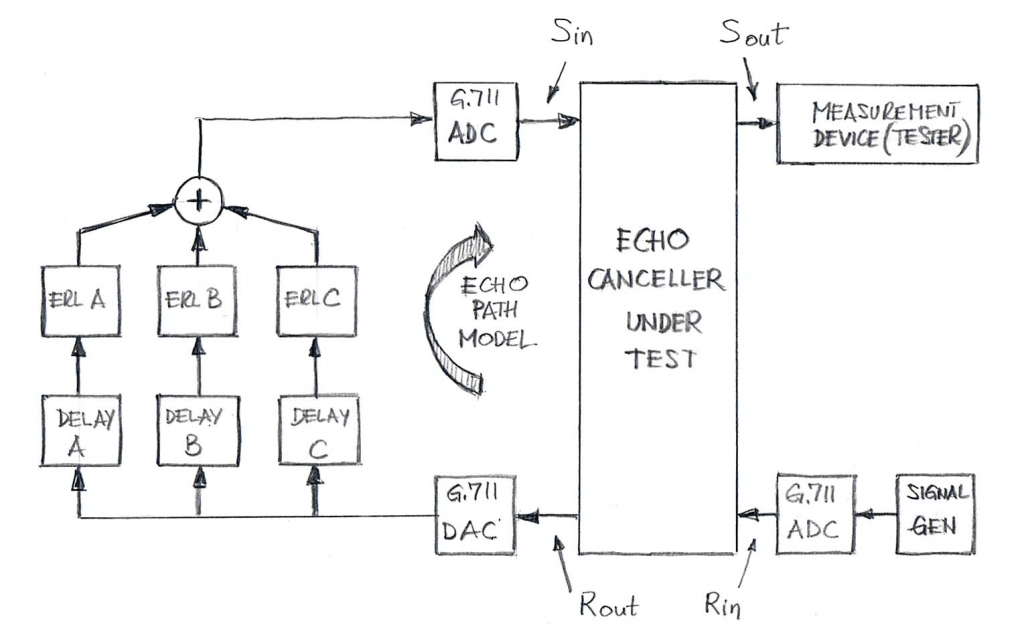
Figure 1 depicts a functional diagram for echo canceller performance evaluation setup using an example of an echo path model taken from the first group, a “three-branch” echo path model (shown in Figure 2). Only elements related to the echo path model are shown. Notation used in this figure is as follows:
- DELAY A,B,C means, the delay blocks delay signals by A,B,C samples.
- ERL A,B,C, means that the gains (GA,GB,GC) are
- GA=10(-A/20); GB=10(-B/20); GC=10(-C/20);

G.168-2015 Echo Path Models
The second group of echo path models represents cases closely related to “real life” situations. There are 8 defined models mn(k), n=1,2,…,8. All 8 models are defined without any pure delay. If specific requirements/design specification require echo canceller coverage include a predefined pure delay, it has to be added to the model under consideration. Table 1 lists the different echo path models along with their general characteristics.
Table 1: G.168-2015 echo path models and their characteristics
G.168-2015 model | Dispersion (in samples) | Number of reflections |
m1(k) | 64 | 1 |
m2(k) | 96 | 1 |
m3(k) | 96 | 1 |
m4(k) | 128 | 1 |
m5(k) | 96 | 1 |
m6(k) | 120 | 1 |
m7(k) | 96 | 2 |
m8(k) | 99 | 2 |
Figure 3 illustrates one of the G.168-2015 models, model m7(k), by showing its time waveform and amplitude characteristics (in relative dB values). This model represents two reflective parts overlapping each other.

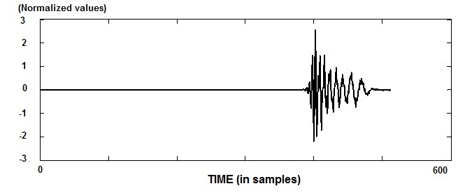
In the case of echo canceller requirement to cover specific echo path delay up to, say 64 milliseconds, the echo path models should be extended accordingly in order to adequately verify the echo canceller product. One direct method of extending echo path models is to add a pure delay for the total echo path model extends up to 64ms. An example of such an extension is shown in Figure 4 where model m4(k) is used. Assuming Fs of 8kHz (narrowband case), the echo path delay of that model is 16 milliseconds. By adding pure delay of 48 millisecond in front of m4(k), the extended model covers 64 millisecond time segment. The echo canceller in consideration is supposed to pass all G.168-2015 tests with this extended echo path model.

VOCAL’s LEC/NEC software solutions are designed to pass and exceed the G.168-2015 requirements using any echo path model defined by G.168-2015 as well as customer models, provided they fit to the echo path coverage of the echo canceller. Please contact us to discuss G.168 echo canceller requirements for your application.