This note as a extension of Ref.[1] (“On Non-Linear AEC”) and it expands on alternate AEC architectures that have recently been examined.
The concept of the Non-Linear Acoustic Echo Cancellation (NLAEC) has been known for years. In the early days of Acoustic Echo Cancellers, the non-linear approaches were practically very limited due to insufficient processing power of embedded computing infrastructure (and, specifically, Digital Signal Processors, DSP) cf. Ref.[2].

The main reason for modeling the echo path using non-linear representation (cf. Ref. [3]) is a realization that the echo path components are non-linear by nature and by approximating the non-linear system identification using a linear system has its adverse consequences such as the limited degree of cancelling the echo and this translates into the limited Echo Return Loss Enhancement (ERLE).
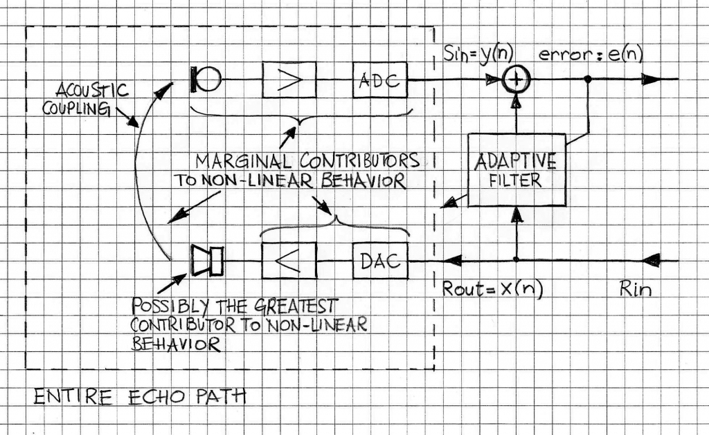
In Figure 1, a high-level block diagram of the adaptive part of an AEC and the echo path is shown. Echo path components contributing, with different degree, are highlighted.
There are several sources of the non-linear behavior of the entire echo path, as seen from the input/output relationship. By far, the greatest possible contributor to the non-linear behavior of the echo path is the loudspeaker. Particularly in the case of inexpensive audio terminals, the loudspeaker is the “weakest point” of the desirably linear input/output relationship (where x(n) is the input and y(n) is the output). Non-linear behaviors of the loudspeaker’s membrane as well nonlinearity of the magnetic flux are some of the specific reasons as to why the loudspeaker produces nonlinear distortions of the input signal. Other sources of non-linearity are marginal in comparison. Even in the case of very inexpensive components used in manufacturing an audio terminal non-linear distortions produced by the microphone and its amplifier are very small when compared to typical distortions produced by the loudspeaker. The non-linearities of wave propagation constituting the acoustic echo path between the loudspeaker’s membrane (a.k.a. diaphragm or, simply, cone) and the microphone are also very marginal contributors to the signal distortions, as least for typical values of the acoustic pressure produces by the loudspeaker’s membrane.
The entire echo path can be represented as a non-linear system with input x(n) and output y(n) by the Kth order Volterra series
with
...
where the upper summation limit, N, corresponds to the length of the entire echo path.
Equation 2 represents the linear case. Most of the acoustic echo cancellation solutions are based on that (i.e., they are based on the assumption that the echo path behaves as a LTI system. Often that assumption leads to the approximation that is too coarse or inadequate from practical viewpoint.
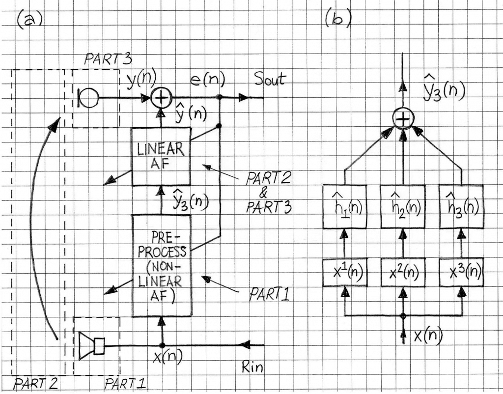
In most of the NLAEC solutions the value of K (the Volterra series’ order) is kept very small. One of the compelling reasons for that is the fact that the computational cost related to the implementation of the NLAEC is significantly higher than in the case of a “standard’, i.e., linear, AEC. Since the cost goes up proportionally to O(NK) (as, for example, in the case of the NLMS algorithm, which is a low-cost adaptive algorithm), thus that cost may become prohibitive even for very small values of K. K=3 is considered the bare minimum for the non-linear approximation because of the physics of the typical non-linear effects taking place when considering in the entire acoustic path (cf. Ref. [4],[5]). Therefore, there has been substantial effort to reduce the computational complexity while still keeping the cubic approximation. For example, Ref. [6] proposes an attractive compromise in a form of a pre-processor which models Part 1 of the entire echo path, that is the “down-link” part including the loudspeaker – see Figure 2.

There are other solutions that mitigate, at least partially, the high cost of implementing NLAEC. For example, the method published in Ref.[7] uses the frequency-domain block adaptive algorithm taken from the conventional time-domain LMS algorithm, computes the time-domain Volterra filter output and estimates the frequency domain block gradients by utilizing the overlap-save method.
VOCAL’s Linear Acoustic Echo Canceller design has been successfully tested in typical acoustical environment and deployed widely. It is ported onto any of the typical DSP processors. If required, the 2nd-order and 3rd-order Volterra kernel parts can be added to the C-based code; though practical realization will require that there is adequate CPU performance to support the non-linear version of the AEC. Contact us to discuss your AEC application with our engineering staff.
More Information
References
- On Non-Linear AEC
- Nonlinear Acoustic Echo Cancellation, André Kaup, 2014;
- The Volterra and Wiener Theories of the Nonlinear Systems, by Schetzen, M., Robert E. Krieger Publ. 1989
- NONLINEAR ACOUSTIC ECHO CANCELLATION WITH 2ND ORDER ADAPTIVE VOLTERRA FILTERS, Stenger, A. et el, University of Erlangen-Nurnberg, ICASSP ’99, vol.2.
- Stochastic gradient based third-order Volterra system identification by using nonlinear Wiener adaptive algorithm, Chang, S.-L. and Ogunfunmi, T.,; IEEE Proceedings – Vision Image and Signal Processing 05/2003;
- ROBUST AND LOW-COST CASCADED NON-LINEAR ACOUSTIC ECHO CANCELLATION, Mossi, M.I., et el., IEEE ICASSP, 2011; pages 89 – 92.