In many Telecommunication applications the Acoustic Echo Canceller block is combined with the Noise Reduction block. One motivation for arranging both blocks into one bigger DSP-based system is the realization that in most cases the echo signal produced at the near end of the voice channel is also combined with environmental noise that leaks into the voice terminal’s microphone. Thus both needs, (1) removal of the echo signal and (2) removal of the noise signal from the transmit signal, are in many practical scenarios equally important from the user’s experience viewpoint.

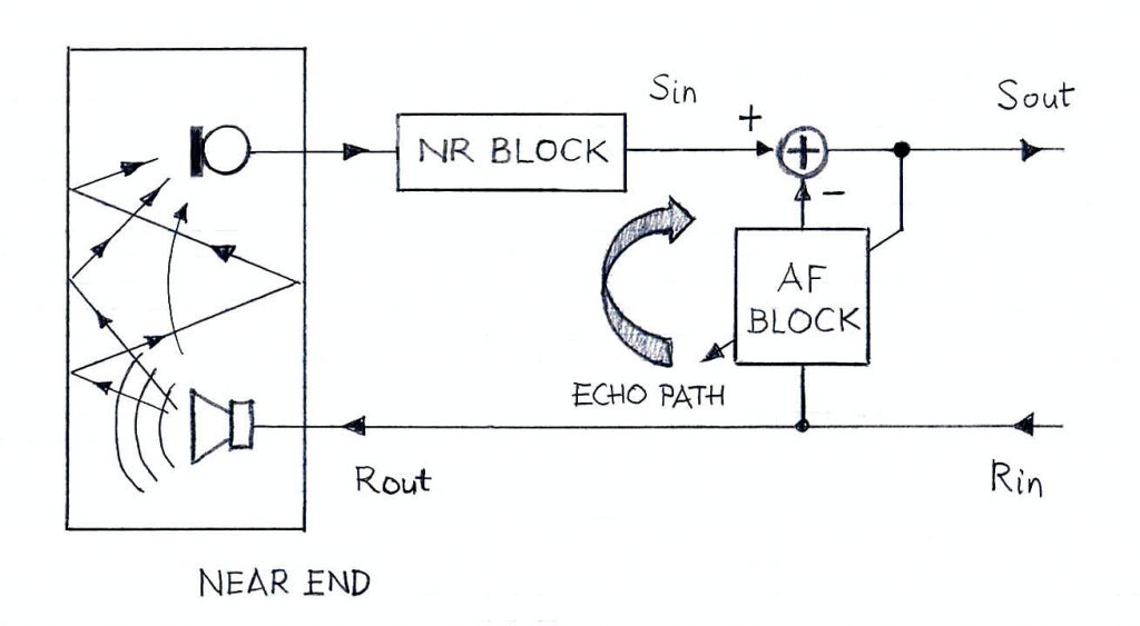
Figure 1 illustrates one of the system block diagrams outlining, using high-level representation, the discussed dual configuration: AEC and NR. In this configuration, the NR block is included in the echo path. Since NR is a non-linear system, therefore signal Sin (an input to the AEC, at the echo path side) is polluted with non-linear distortions not only produced by non-linearities included in the near-end echo path (and mostly produced by the loudspeaker) but also produced by the NR block.
Combined AEC and NR – Alternate Configurations
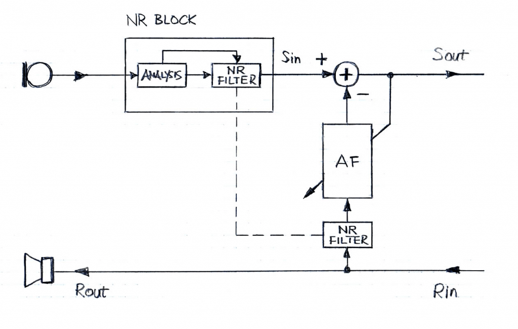
To partly alleviate the concern regarding introduction of additional non-linear distortions, the first alternate configuration is depicted in Figure 2. By introducing a copy of the NR filter at the entry to the adaptive filter box, the echo path replica is closer, in terms of non-linear distortion contents, to the Sin.

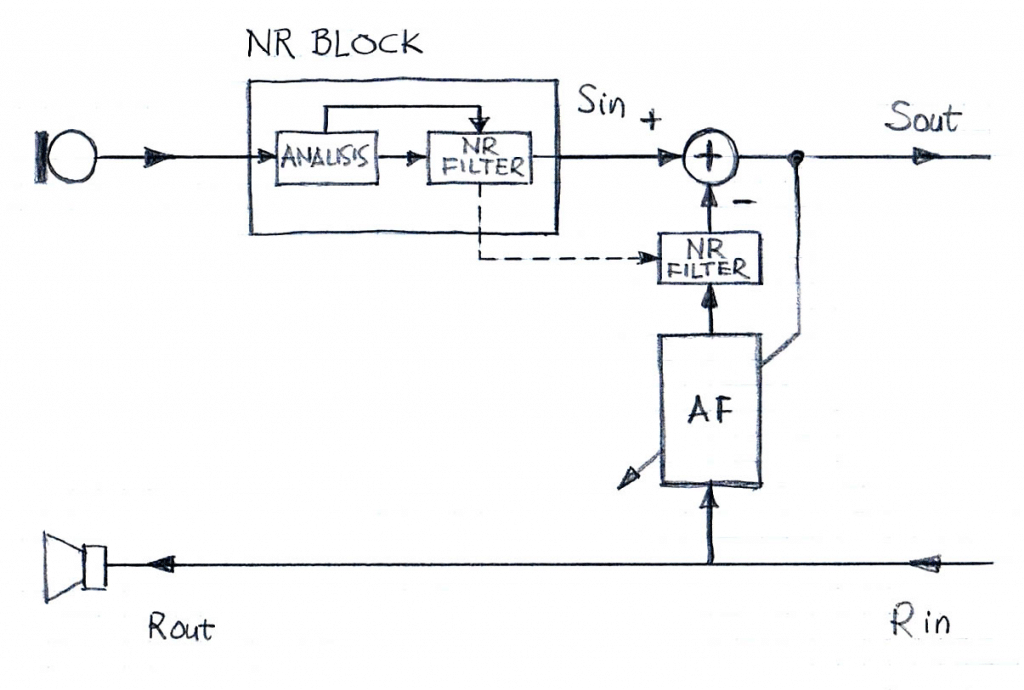
In Figure 3 the second alternate configuration is available is depicted. The difference between configuration shown in Figure 2 versus the one shown in Figure 3 appears to be minor. Yet, it is worth noting that in the configuration shown in Figure 3, the input to the echo path is identical to the input to branch (AF + NR block) where the echo replica is produced. This has a beneficial influence on the adaptive filter coefficients.

In both cases (Figure 2 and Figure 3), additional placement of the NR filter tends to improve filter convergence when compared to the case presented in Figure 1. Consequently, in these configurations it is expected that the residual echo is reduced (when compared to the case in Figure 1).
Figures 1, 2 and 3 depict cases where the NR filter is placed before the AEC, and thus some degree of non-linear distortions affects adversely the AEC operations. On the positive side it is noted the near-end input to the echo canceller has better SNR, as a direct result of the NR operations.

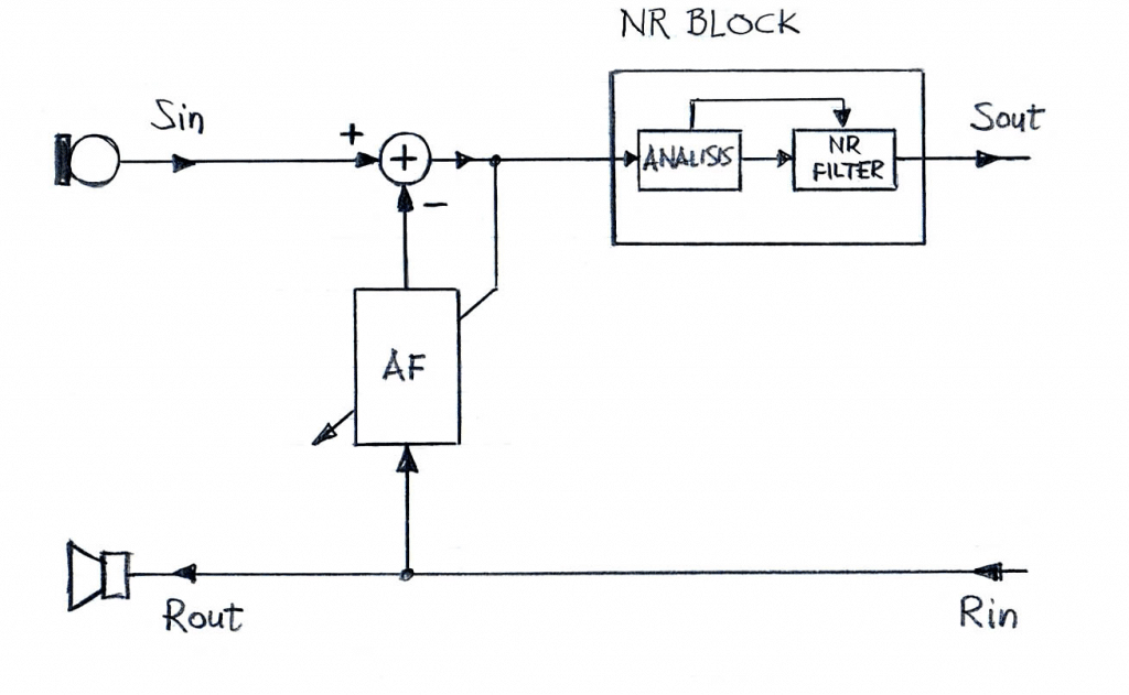
The configuration depicted in Figure 4 does not show any additional sources of non-linear distortions introduced to the echo path (except for the “native” non- linear distortions produced in the echo path (culprit: loudspeaker). On the other hand in this configuration, the AEC operates on the originally noise-polluted Rout signal which makes the filter adaptation slower and shallower.
Technical reports and papers tend to agree that none of discussed configurations is universally better than another, irrespective of the specific algorithms used. For example, one of the popular adaptive filter algorithms, NLMS, is known to perform well in either case (meaning, when NR in the echo path versus NR outside of the echo path) in typical use cases.
VOCAL Technologies’ AEC and NR solutions can be configured in flexible fashion and any of the discussed specific system arrangements is offered as a custom solution. Please contact us to discuss your requirements for acoustic echo cancellation and noise reduction.