An important application of microphone array beamforming is its use in monitoring a speech source in the far field. Typical examples include surveillance, crowded vicinities such as a sports stadium or restaurant, gaming rooms etc. These settings pose a challenge in most beamforming solutions because of the inherent presence of both ambient noise and interfering speakers. The task at hand is to isolate a speaker from a particular direction or person whilst suppressing all other speakers and noise. Typical solutions to this problem is the use of an endfire configuration with spatial beams pointed at the direction of interest.
Consider a  microphone array as shown in Figure 1:
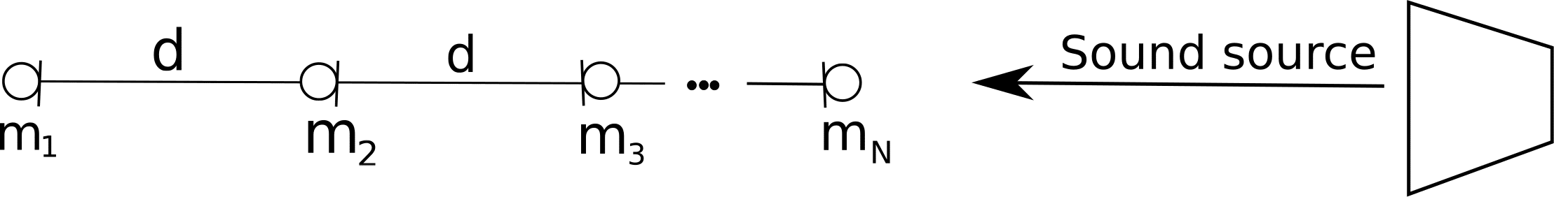
Figure 1: N microphone array
Theoretical bounds can be generated for beamforming gains with increasing number of beams. The bounds however are based on a number of assumptions which include spatially diffuse noise and uncorrelated interference sources. Most often than not, the noise will not be spatially diffuse but rather directional like heating vents or air conditioners which are strategically placed in rooms. Further, the nature of these rooms make them behave like an echo chamber, resulting in reverberant speech which is correlated with the speech of interest from different directions of arrival. A trade off in design has to be made in designing optimal number of microphones by considering the room, the number of microphones to be used, the form factor of the device and the end consumer. The end consumer is also very important: the solution for a beamforming solution which will be fed to an ASR engine is different from a communication exchange between two human end users.
To illustrate, consider a 2 microphone array and an endfire solution implemented to form a beam at  and a null at
  for three transmitted tones. Figure 2 below, the top row illustrates the spectrogram of a pseudo ideal situation where the signals from a single microphone is delayed by a single sample using a sampling rate of
  and a microphone separation of 21mm. The green plot illustrates a beam whiles the magenta illustrates the null from the opposite direction. There is about
  suppression of the noisy signal. Now compare the top results to the bottom row, where both signals are from the two microphones. It can be seen that the suppression is minimal due to the room echo chamber effect. It should be noted that the signals here are three narrow band tones whilst actual speech is wide band.

Figure 2: Comparison between theoretical and actual beamforming gains
VOCAL Technologies offers custom designed solutions for beamforming with a robust voice activity detector, acoustic echo cancellation and noise suppression. Our custom implementations of such systems are meant to deliver optimum performance for your specific beamforming task. Contact us today to discuss your solution!