We show an approach to beamforming an acoustic source using a circular microphone topology. Consider the circular array illustrated in Figure 1 below and suppose a beamforming solution is desired.
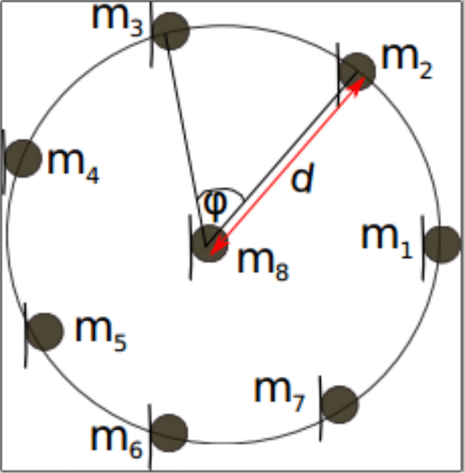
Figure 1: Circular microphone array topology for  microphones,
  .
.
Define the angle of arrival to be the impinging angle at microphone  as
as  , using the line joining microphones
  and
and  as reference. Then by averaging the received signals at all eight microphones, it can be easily shown to that;
 = \frac{1}{8} \sum\limits_{q} X_{q} (w) = X_0 (w) H(w) + \frac{1}{8}\sum\limits_{q} N_q(w)")
where
 = X_0 e^{-jw\tau_{8,q}} + N_{q} (w)")
Here,  is the delay between microphones and
  ,
, ") the effective “sum filter”. can be synthesized as:
the effective “sum filter”. can be synthesized as:
 = \frac{1}{8} + \frac{1}{8} e^{jw \frac{d}{c}\sin{\theta}} + \frac{2}{8} \sum\limits_{n=1}^3 e^{jw \frac{d}{c} \cos{(n\psi)}\sin{\theta}} \cos{\left(w\frac{d\sin{(n\psi)}}{c} \sin{\theta}\right)}")
Suppose we have the angle of arrival, any beamforming algorithm together with filter can be deployed to reduce the noise considerably.
VOCAL Technologies offers custom designed solutions for beamforming with a direction of arrival estimation, robust voice activity detector, acoustic echo cancellation and noise suppression. Our custom implementations of such systems are meant to deliver optimum performance for your specific beamforming task. Contact us today to discuss your solution!
\end{document}