The superdirective beamformer is an optimal technique derived from the minimum variance distortionless response (MVDR) algorithm. This method minimizes the power output and applies a linear constraint in order to obtain an undistorted output signal. These optimizations maximize the directivity index, yielding the solution
 = \frac{\textbf{S}_{NN}^{-1}\textbf{A}\,}{\textbf{A}^H\textbf{S}_{NN}^{-1}\textbf{A}}")
where  is the power spectral density of the input noise, A is the steering vector, and
 ") the frequency dependent weight function. The noise power spectral density matrix can be estimated utilizing the coherence function. Here, we assumed a diffuse noise field using a sphericallyisotropic model,
the frequency dependent weight function. The noise power spectral density matrix can be estimated utilizing the coherence function. Here, we assumed a diffuse noise field using a sphericallyisotropic model,
\;\forall\;n,m")
where k is the wave number and  is the inter-microphone spacing.
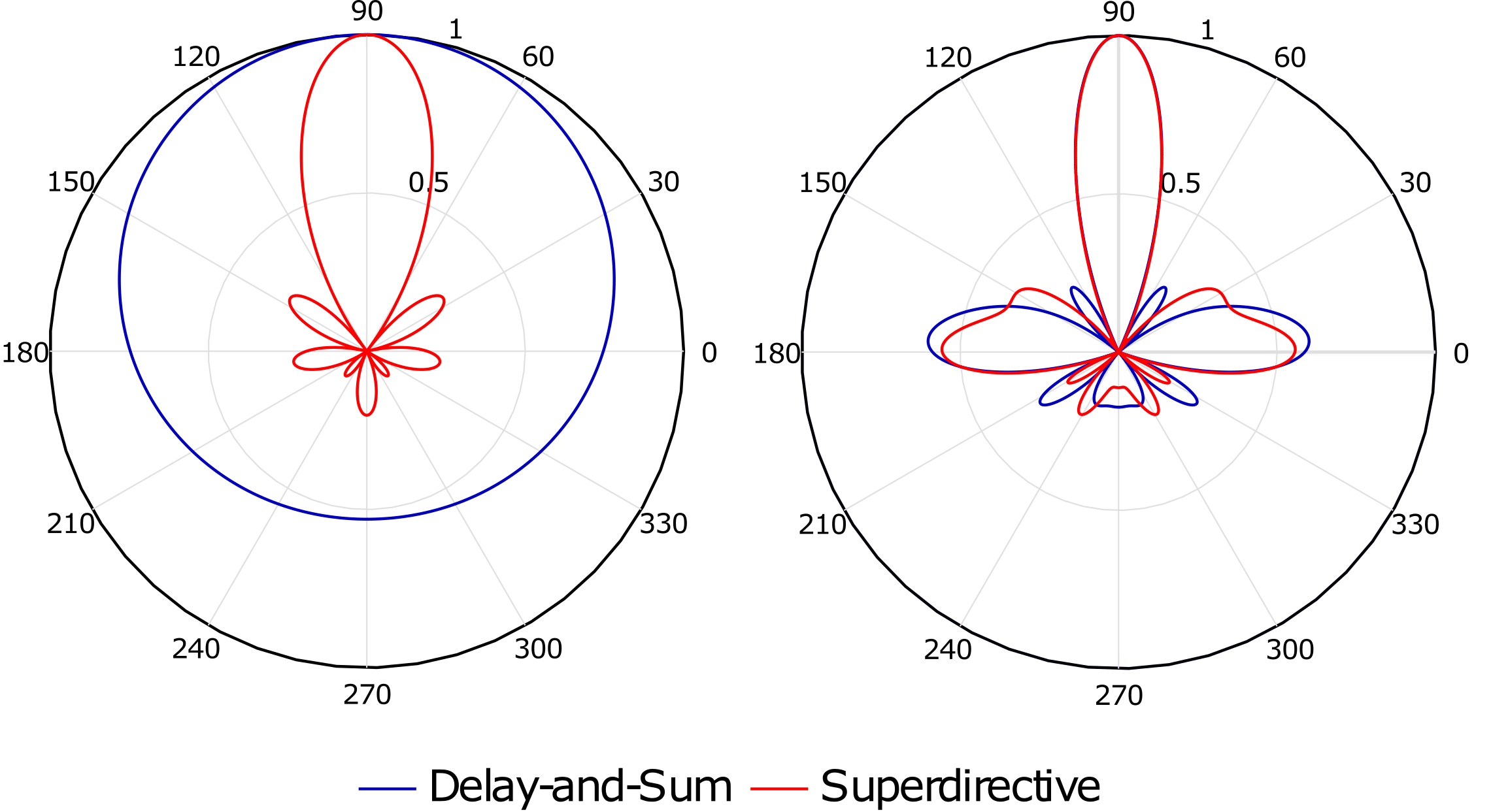
Comparing the superdirective beamformer to the conventional delay-and-sum, we see the differences in the low frequency beam pattern. As seen in Figure 1, the delay-and-sum lacks any beam directivity at 500 Hz, highlighting the inability to suppress low frequency noise sources. The noise suppression
efficiency from both techniques converges in the high frequency range. This threshold is dependent on the geometry and number of microphones in the array. Although a superdirective array yields a highly directive beam at low frequencies, the array is also sensitive to uncorrelated noise, i.e., instrumental noise. To combat this deficiency, loading the diagonal elements of the noise model may be applied to tune to the desired noise gain and directivity index.