Uniform linear microphone arrays have a disadvantage of not being able to distinguish between angles that are offset by  . To solve this problem, uniform circular array topology is utilized to have a full angle view for beamforming. Consider a far field signal source impinging a 3 circular microphone array after propagating through an anechoic acoustic medium as shown in Figure 1:
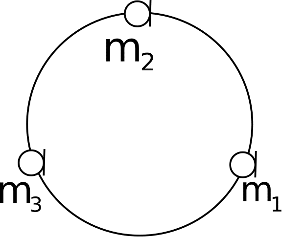
Figure 1: 3 microphone array
The uniformity in the circular array is that the pairwise clockwise consecutive distances are identical. With this configuration, it is easy to show that the delay components between microphone 1 and the other microphones, denoted ![\Delta_{1,i}, i \in [2,3]](https://s0.wp.com/latex.php?latex=%5CDelta_%7B1%2Ci%7D%2C+i+%5Cin+%5B2%2C3%5D&bg=ffffff&fg=000000&s=0 "\Delta_{1,i}, i \in [2,3]") follows:
follows:
= 2 r \sin{\left(\frac{2\pi}{6}\right)} \cos{\left(\frac{\pi}{3} + \theta\right)}")
and
 = 2 r \sin{\left(\frac{2\pi}{6}\right)} \cos{(\theta)}")
where  is the radius of the circle and
  is the angle of arrival. Filter weights,
  are desired such that:
} & e^{-jw\Delta_{1,3} (\theta_1)} \\1 & e^{-jw \Delta_{1,2} (\theta_2)} & e^{-jw\Delta_{1,3} (\theta_2)} \\1 & e^{-jw \Delta_{1,2} (\theta_3)} & e^{-jw\Delta_{1,3} (\theta_3)} \end{bmatrix} {\bf h} = \begin{bmatrix}1 \\0 \\0\end{bmatrix}")
The choice of  determines the shape of the spatial filters that are realized. Setting
 ![[\theta_1 \theta_2 \theta_3]^T = \pi [0 .95 -.95]^T](https://s0.wp.com/latex.php?latex=%5B%5Ctheta_1+%5Ctheta_2+%5Ctheta_3%5D%5ET+%3D+%5Cpi+%5B0+.95+-.95%5D%5ET&bg=ffffff&fg=000000&s=0 "[\theta_1 \theta_2 \theta_3]^T = \pi [0 .95 -.95]^T") for instance will lead to the filters shown in Figure 2 below.
for instance will lead to the filters shown in Figure 2 below.
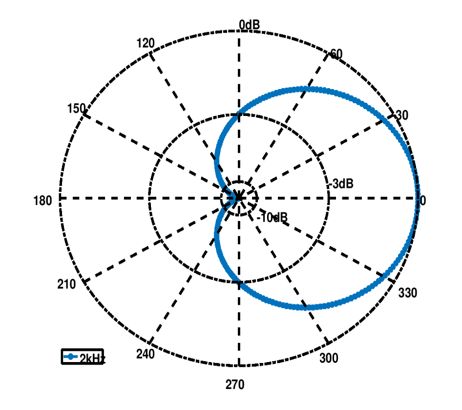
Figure 2: Spatial filtering with circular uniform array.
VOCAL Technologies offers custom designed solutions for beamforming with a robust voice activity detector, acoustic echo cancellation and noise suppression. Our custom implementations of such systems are meant to deliver optimum performance for your specific beamforming task. Contact us today to discuss your solution!