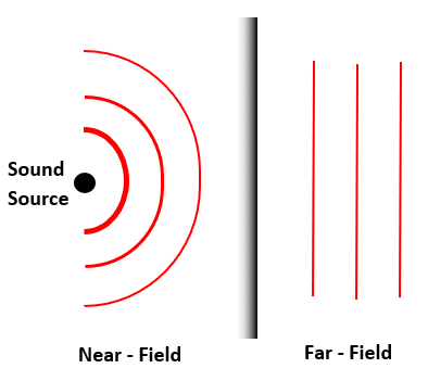
The far-field sound propagation model is often used in the design of beamforming algorithms for microphone arrays because the sound sources are often located at a much greater distance from the array than the size of the array. In the far-field model, sound propagates as a plane wave and the decay of the magnitude of the signal energy from the sound source is uniform across the array.
While this sound propagation model may hold in practice, the microphone channels may not be perfectly matched. Manufacturing tolerances of the microphones, ADCs, and preamplifiers create variability among the array channels, that make the uniform signal energy assumption invalid. In addition, final product designs enclose microphone arrays in a mechanical housing, which may not be acoustically transparent. This channel mismatch will have a negative impact on the white noise gain (WNG) and the directivity index (DI) of the beamformer.
In order to minimize the magnitude channel mismatch, a calibration procedure is required. Calibration methods can be performed at the factory or during an installation, but a real-time calibration solution is preferred. One solution is to normalize all of the microphone signals based on the long-term power signal levels. The gain value for the microphone with the minimum signal energy is set to 1, and the gain value for the maximum microphone is set to  . The formula of the gain factor for the magnitude calibration is:
+G_{min}}")
Since the channel mismatch can be frequency dependent, this calibration should be performed and applied independently in the frequency domain.