When designing a multi-microphone sound capture device for full-duplex communication and/or voice control products, it is important to understand how the microphone array geometry affects beamforming performance. The most common geometry beamforming designs are uniform linear arrays (ULA) or uniform circular arrays (UCA). For a given number of microphones, maximum directivity can be achieved in the endfire direction (0 degrees) of a ULA. Figure 1 below shows the polar plot of an 8 element ULA with interspacing of 5cm, and an 8 element UCA with a radius of 5 cm.
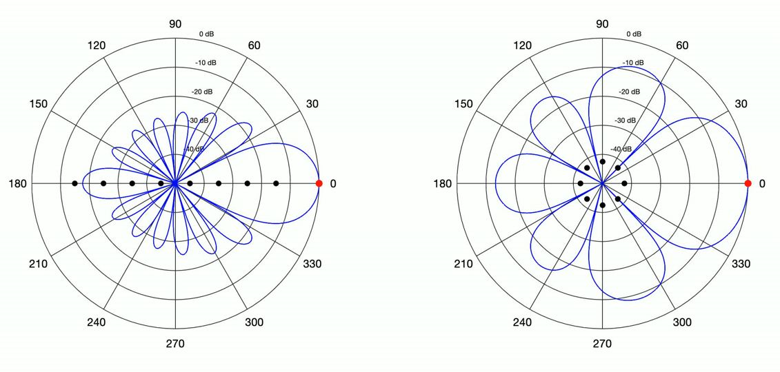
As it can be observed that the circular array has a wider mainlobe, and larger sidelobes than the linear array. In Figure 2, shows the polar plot of same arrays, but now the look direction is in the broadside direction (90 degrees).
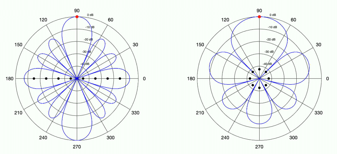
The beamforming pattern for the UCA is identical for both the endfire and broadside directions. The ULA beamwidth has widened, and has an ambiguity lobe at 270 degrees, and provides no front-to-back enhancement.
Therefore, if the application of the product design has the desired sound source in a known fixed look direction, it is best to use a ULA with an endfire orientation. If the desired sound source can be located in any direction 360 degrees around the device, it is best to use a UCA to due to its rotational invariance.
VOCAL Technologies offers custom designed solutions for beamforming with a robust voice activity detector, acoustic echo cancellation and noise suppression. Our custom implementations of such systems are meant to deliver optimum performance for your specific beamforming task.