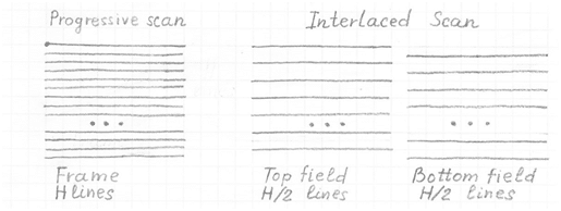
Video displays use one of two scanning methods to draw the picture on a TV screen: interlaced and progressive. Interlaced video was essentially the only video signal utilized in analog television for many years. Interlaced video was used in lieu of progressive to reduce flickering on the screen of analog CRT (Cathode Ray Tube) TV sets. This also preserved a certain bandwidth of transmitted video signal.

A progressive video sequence consists of a sequence of full frames of the particular size, called resolution width x height (WxH) in pixels, followed by the particular frame rate (number of frames per second). A video frame consists of H lines that are basically horizontal rows of pixels. Each row has W pixels. Each frame may be considered a still image corresponding to a particular moment of video.
Interlaced video sequence is a sequence of fields where a field is a subset of a frame and consists of odd or even lines of the frame. There two types (or polarity) of fields:
- top field (or field A) that consists of even lines (line numbering starts from 0)
- bottom field (or field B) that consists of odd lines (line numbering starts from 0)
In an interlaced video sequence, full frames are not from the same moment of time, however the individual fields are taken from the same moment.
Modern TV sets (LCD, DLP and Plasma) are based on progressive scan. It means that interlaced video before displaying on the monitor has to be deinterlaced, i.e. from the sequence of fields for the sequence of full frames to be created.
Methods for Deinterlacing
There are number of methods to create a deinterlaced frame from field(s).
Line doubling(“Static mesh”, Weave)
This method generates the missing pixels by copying the corresponding pixels from the previous field. For video without any motion, it creates the best quality full frame video. The drawback of this method is that frames show a very visible “feathering” artifact in areas of high or even slow motion.
Vertical interpolation from the same frame (Bob)
The vertical interpolation method interpolates the missing pixels from the pixels located directly above and below them in the same field. The drawbacks of this method are
- severe reduction in the vertical resolution of the output frames
- visible flickering or scintillating effect, especially for slow motion video.
Weighting sum of static mesh and vertical interpolation
This method is a combination of two previous methods as a weighting sum of corresponding pixels from the previous field and interpolated value from the pixels located directly above and below them in the same field. Both “feathering” and scintillation perceptual artifacts are reduced by choosing the values of weights. This method allow to improve the quality but still reduce the vertical resolution for video with no motion and has some level of both “feathering” and scintillation artifacts.
Weighting sum of static mesh, vertical interpolation and high vertical frequencies from the previous frame
This method is based on the previous method except the third component of the weighting sum is introduced. This component is high frequency component of vertical direction from the previous field. The compromised quality between “feathering”, scintillation artifacts and vertical resolution reduction is substantially improved compared to the previous method.
Motion adaptive deinterlacing
Motion adaptive deinterlacing is a big breakthrough in video quality compared to the previous methods. Essentially, this method is the same as the previous method but instead of constant weighting, dynamic weights are used. The weight values are functions of measured pixel based motion. For video without motion, it is possible to reach the quality of line doubling. For high motion video, the “feathering artifact” does not exist. For slow motion, the “feathering” and scintillation artifacts are reduced.
Motion adaptive directional deinterlacing
Adaptive directional deinterlacing is based on the previous adaptive method where for the current frame interpolation, instead of vertical interpolation, the directional interpolation is used. The direction of image pattern or edge in the area of interpolating pixel has to be detected by the directional detector. Directional deinterlacing decreases the “jaggedness” artifact for diagonal edges and textures.
Motion compensative directional deinterlacing
Compensative directional deinterlacing is the extension of the previous method, however instead of detecting the scalar motion value, the motion vector for a current deinterlaced pixel is estimated. The pixels from the previous field that participated in deinterlaceng are taken not from the same location but from the location determined by the motion vector.
The methods listed above are applicable both for luma and chroma pixel deinterlacing.