In real time audio applications such as acoustic echo cancellation in teleconferencing, it is important that filtering is done quickly and without being noticed by the users. As [1] explains, this points to finite impulse response (FIR) filtering being ideal. Consider that a quick filter will be characterized by perceptual instantaneousness. This means that given your sampling rate, the length of your filter must be less than the length of the impulse response of the human ear.
Audio FIR Filter
The maximum length of an audio FIR filter can be found by taking the reciprocal of the smallest critical bandwidth of hearing. Physically, this corresponds to the smallest band of the basilar membrane that any signal excites. For a complex sound like speech, this critical bandwidth illustrates how far apart different frequencies must be spaced in order to avoid masking. These critical bands are usually measured around a standard center frequency, and are spaced nearly a third of an octave apart. As frequency increases, the critical bands become wider.
The smallest critical bandwidth is 100Hz centered around 150Hz, with a lower cutoff frequency of 100Hz and an upper cutoff of 200Hz [2]. So a sampling rate of 44KHz will necessitate a filter no bigger than 440 taps. 440 taps means 440 degrees of freedom to design your filter, so there is still plenty of magic that can be done. Some of this magic is accomplished through the use of adding the constraint that the filter be linear phase.
What is Linear Phase?
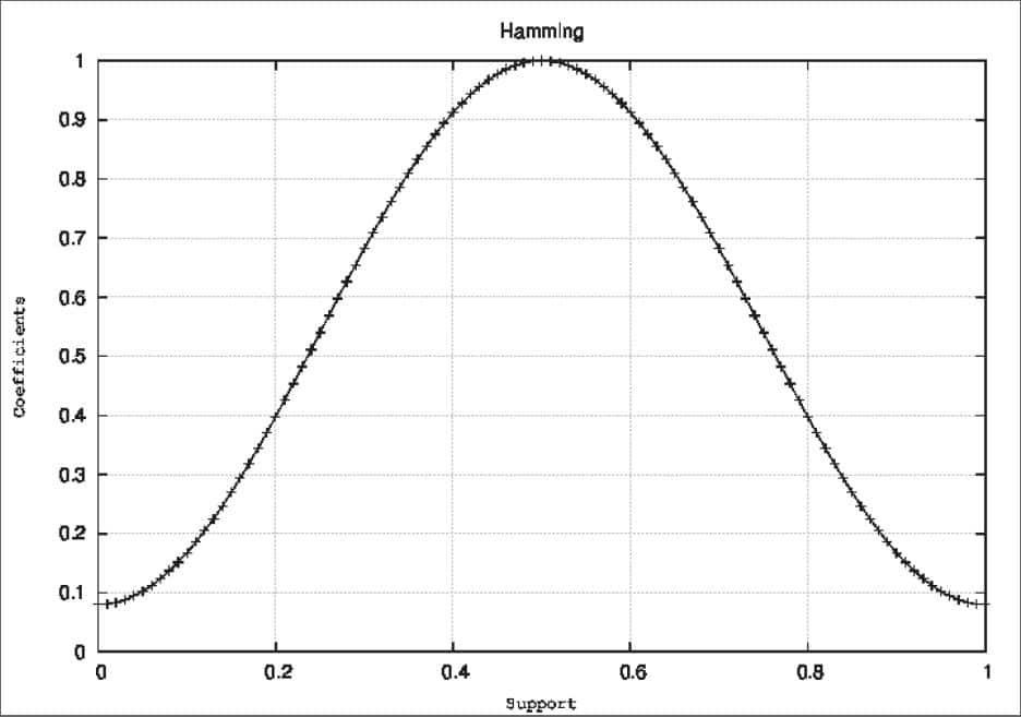
Linear phase filters are practical realizations of zero phase filters. A zero phase filter is a filter that has symmetry about the origin. Thus when using a zero phase filter, one must take negative indices into account, which is rather tedious and is prone to error. To make things easier, we instead make the filter symmetric about some non-zero point. What results is a linear phase filter as shown in Figure 1:

Linear phase filters are important for audio filter design because passing a signal through a linear phase filter will delay all of the frequency components by the same amount, thus leaving the structure of the signal intact, which will preserve speech intelligibility. To understand how phase effect delay, it’s quite common to start by looking at the frequency response of the ideal delay system h[n] = δ[n – nd]:
This behavior is due to the sampling property of the delta function. We can see that the phase is then:
Which is a linear function of frequency. Thus, time delay and linear phase are inexorably linked. If you still don’t believe, consider what happens when we put a signal ![]() through the ideal delay system. The output is:
through the ideal delay system. The output is:
This has frequency response:
As the equation shows, regardless of what the frequency response of the input ![]() is, it is shifted linearly by ωnd, while the time domain signal is shifted by nd. Again, time delay and linear phase are inexorably linked. With this in mind, it will be useful to examine some different types of filters that will give us a linear phase response. First, we will examine an example of a linear phase FIR filter from [3].
is, it is shifted linearly by ωnd, while the time domain signal is shifted by nd. Again, time delay and linear phase are inexorably linked. With this in mind, it will be useful to examine some different types of filters that will give us a linear phase response. First, we will examine an example of a linear phase FIR filter from [3].
Linear Phase FIR Filters
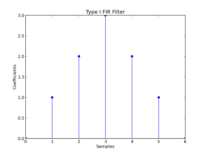
There are actually four types of linear phase FIR filters are appropriately named Type I-IV. These filters are categorized by whether they have an even or odd length, and whether they are symmetric or antisymmetric. In all cases, we will define the center of symmetry to be M/2 where M – 1 is the length of the filter. Since the filters will have essentially the same shape on either side of the center of symmetry, we can think of each as a filter delayed by M/2 . As an example, consider the first type below.
Type I FIR Filters
Figure 2: Type I FIR Filter
As the above figure shows, Type I FIR Filters are odd length filters with a symmetric impulse response given by:
Most generally, these filters can be represented as:
Where:
For the example above, the frequency response is:
Optimal Filter Design
Now that we know how to analyze our FIR filter, we will consider a basic form of optimal filter design. In the z-domain or the frequency domain, the first step is to place your coefficients. By assuring a smooth interpolation between the points, this is akin to hand-drawing the desired response. Unfortunately, Heisenburg tells us that this method may not give us finite support in the time domain. In other words, the filter length will be infinite. To solve this problem, we simply multiply the signal we get through an inverse Fourier transform by a window, thus assuring finite support. However, this will lead to infinite support in the frequency domain and thus might shift your frequency response from where you originally designed it. Clearly, this method is suboptimal, but can be improved first by carefully choosing the window for the specific application and second by applying an optimization procedure. Let your chosen amplitude response be denoted Ad(ω), the resulting amplitude response be denoted A(ω), and the error as E(ω). We then formulate the lp minimization problem as follows:
Where w is a positive weighting function. Denoting the cosine matrix for the Fourier transform as C, and playing the ws on the diagonal of a matrix called W, we can then find the optimal weights iteratively as:
This is the basic algorithm called IRLS, but it is not perfect. Seeing how am requires matrix inversions, this method will not always be stable. Instead, [4] discusses other procedures that improve on this method called the RUL and BBS algorithms. The basic idea for improvement comes from assuring stability by specifically formulating the weights, or formulating a recursive update equation for am.
References
[1] J. O. Smith, Spectral Audio Signal Processing, http://ccrma.stanford.edu/jos/sasp/, Dec. 2011, online book.
[2] B. Traux, Handbook for Acoustic Ecology, 2nd ed., World Soundscape Project, 1999
[3] A. V. Oppenheim, R. W. Schafer, Transform Analysis of Linear Time-Invariant Systems, in Discrete Time Signal Processing, 2nd ed. Upper Saddle River, NJ: Prentice-Hall Inc., 1999, ch. 5, sec. 7, pp. 298300.
[4] R. A. Vargas, C. S. Burrus, Adaptive Iterative Reweighted Least Squares Design of Lp FIR Digital Filters, Proceedings of the IEEE International Conference on Acoustics, Speech, and Signal Processing., Phoenix, AZ., 1999


