ETSI document “Speech Processing, Transmission and Quality Aspects (STQ); Speech quality performance in the presence of background noise; Part 1…” (ETSI EG 202 396-1 V1.2.2) provides specific guidance regarding setup of audio testing facility (a.k.a. ETSI room) whose acoustic parameters are intended to represent a “standard office room”.
The main purpose of the ETSI room is to provide an acoustical environment for acoustical evaluation of audio-related designs and audio products such as smart phone sets, BlueTooth head sets and similar devices. For this purpose the central part of the audio test equipment is an artificial head (AH). One example of AH is a Brüel & Kjær’s mannequin called Head and Torso Simulator, which, in technical parlance, is simply called HATS.
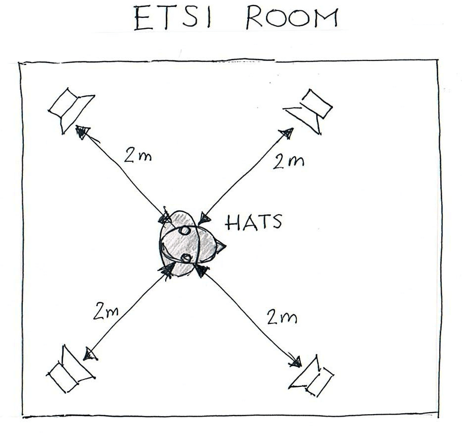
Figure 1 shows a sketch of an ETSI room with four loudspeakers located at corners and a subwoofer located between a pair of loudspeakers. The HATS is located centrally with respect to the four loudspeakers. In practice, the ETSI room is used for evaluation of audio-related designs and audio products related to laptop computers, tablets or alike that do not require HATS.
The ETSI room is by no means a substitute for an Anechoic Chamber or Semi-Anechoic Chamber. It is merely an agreed part of acoustic/audio facility that serves as a “typical” or “standard” office room, for the purpose of evaluating audio designs and audio products typically intended for consumer markets worldwide.
One of the typical uses of ETSI room requires acoustic noise files be played back through the speakers. In order to faithfully (or close to “faithfully”) represent effects of noise distractors (or simply, noises), processing of equalization and calibration is essential. Also, the AH has to be equalized; in general, “the equalization is done binaurally: the two left-hand speakers are equalized to the left channel of the artificial head and the right-hand loudspeakers are equalized to the right channel of the artificial head.” (ref.: ETSI EG 202 396-1 V1.2.2, Sub-section 6.3).
There are several methods used for equalizing ETSI speakers. They can be either implemented by the use of equalizers (i.e., special banks of narrow-band filters) through which the audio files are played back, or the equalization can be done by properly pre-filtering the audio files by inverse filters. With this respect, typical DSP methods can be used. These are, but not limited to, Yule-Walker algorithm (in MATLAB, yulewalk()), frequency-domain LMS-based method, a FIR arbitrary-shape filter design using the frequency sampling method (in MATLAB, fir2() ). Since linear-phase methods are preferred (yet hardly mandatory), the latter method is one of the justified choices.

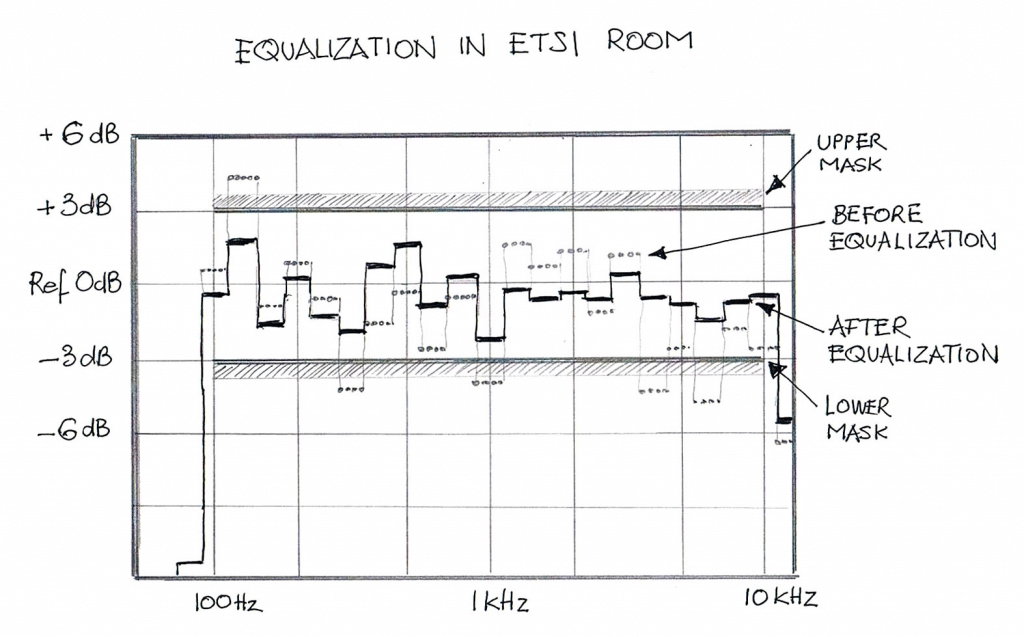
The ETSI normative document refers to equalization in 1/3rd octave bands, and, for comparison and verification, in 1/12rd octave bands. The equalization template (a.k.a. mask) for ETSI loudspeaker equalization (excluding the subwoofer) allows for +/-3 dB departures (with respect to relative reference of 0 dB) across frequency band [100 Hz, 10000 Hz]. If digital recordings are produced in the wideband (i.e., with the sampling frequency, Fs, of 16 kHz), then the equalization frequency band is narrowed and limited by the Nyquist frequency (i.e., by Fs/2 = 8kHz). Figure 2 illustrates one of the examples of the effect of equalization (i.e. 1/3rd octave bands) of ETSI room loudspeakers.