The topic of echo canceller stability is broad and it encompasses specific subjects such as IIR-based adaptive filtering (cf. Ref. [1]) , FIR-based adaptive filtering, near-end and far-end system stability (cf. Ref. [2, 3]), to mention a few. In this note we limit our considerations to FIR-based adaptive filtering stability using, as an example, the LMS algorithm.
While any LTI system that is represented in a form of a FIR filter is stable in BIBO (bounded input bounded output) sense (as its transfer function does not have poles within the unit circle), it may become unstable if its coefficients are dynamically changing, according to some specific rules. So, the instability may be caused by the filter coefficient changes, not the by the filter type.
A FIR adaptive filter is thus becoming stable after it reaches the state of full convergence (when its coefficients are semi-static, or, practically speaking, constant). However, during the adaptation process, particularly at its beginning, the filter may become unstable in BIBO sense. This instability may be primarily caused by two reasons, of which the first one is more common and critical than the other. The first is related to the poorly chosen adaptation step. The second is the limited precision of the adaptation formula implementation due to limited-precision fixed-point representation of constants and variables. We will focus our attention on the former.
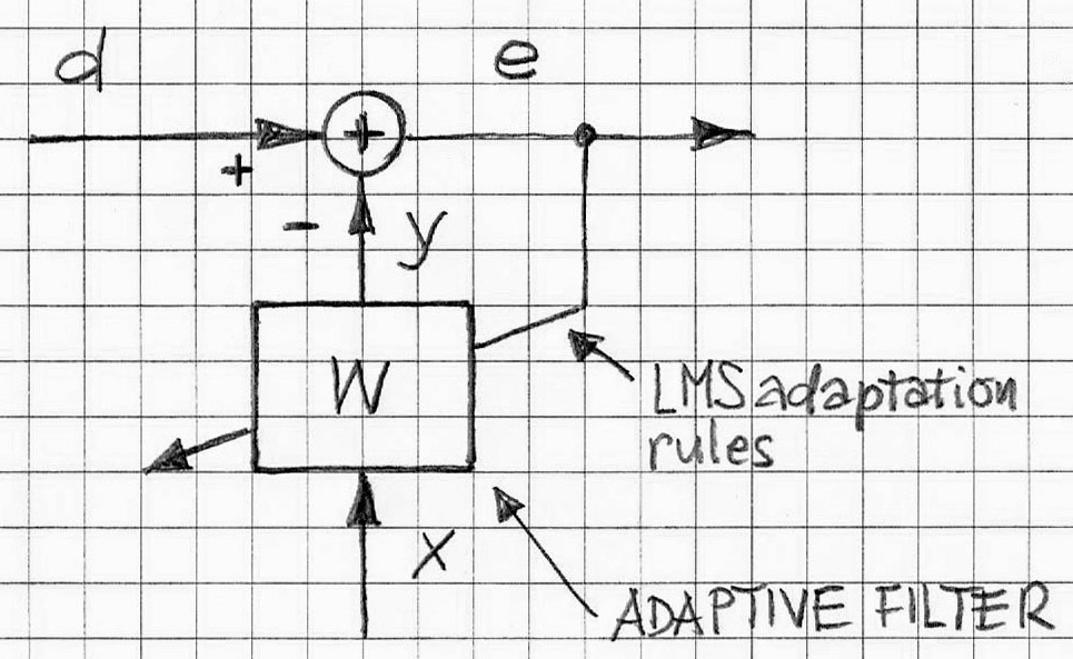
Let us consider an adaptive filter (whose block diagram is depicted in Figure 1) with governing equations based on the LMS algorithm.

In Figure 1 the notation of signals around the adaptive filter are:
- d: target/desired signal
- y: replica of target/desired signal
- x: input to the adaptive filter
- e: error signal
- W: FIR adaptive filter (in this case, LMS adaptive filter)
Equations 1a and 1b reflect the input/output relation for the standard FIR filter with adjustable weights {wj(k)}, j=0,1,…,N-1; N is the total number of filter weights (or coefficients), i.e., the length of the FIR filter. The equations are as follows:
or, using vector notation, we have
y(k) = XT(k). W(k). (1b)
In the case of the most popular adaptation algorithm, LMS algorithm, the adaptation formula for W is given by the following (cf. Ref. [4]):
W(k+1) = W(k) + m. X(k) .e(k), (LMS adaptation formula) (2)
where
e(k) = d(k) – XT(k).W(k), (error signal) (3)
X(k) = [x(k), x(k-1),…, x(k-N+1)]T . (input vector) (4)
and W = [w0,w1,…,wN-1]T, (FIR filter weights) and m is the LMS adaptation step.
Depending on value m the adaptation process is faster or slower. For sufficiently small values of m and limited values of X, the adaptive system is stable in the BIBO sense.
However, if value m is not sufficiently small, the system becomes unstable, and as result, the error signal becomes unbounded.
The condition for stability of the LMS algorithm is as follows (cf. Ref. [5]):
where λmax is the largest eigenvalue of the correlation matrix R of the tap-input vector X.
For example, if X is a white noise then its N x N correlation matrix R becomes
R = diag (σ2, σ2,…, σ2),
where σ2 is the variance of a sample of the process X. This correlation matrix R has a single degenerate eigenvalue equal to the variance σ2 with multiplicity of N (ibid).
With the white-noise input, the LMS is stable if
In more general case, a wide-sense stationary X with real values, the correlation matrix R in expanded form is as follows
where r is autocorrelation function of X. That is
r(k) = E[x(n).x(n-k)], (8)
where E[.] is statistical expectation operator.
In practice, when X cannot be adequately represented by the white noise, it is very inconvenient to compute eigenvalues and determine what the λmax is. Therefore, it is beneficial to use some simple working rules leading to “safe” choice of the LMS step size m.
A conservative estimate of λmax is the trace of matrix R (often denoted as tr[R]); tr[R] is the sum of all diagonal elements of the matrix R. For a wide-sense stationary process the correlation matrix is not only positive definite but also Toeplitz, with all elements of the main diagonal equal to r(0). Therefore
tr[R] = N.r(0). (9)
By employing Eq.(8) we can express tr[R] as follows:
Thus, for ergodic processes, Formula (10) represents ”tap-input” power, that is the sum of the mean-square values of the tap inputs, x(j), as per XT(k) = [x(k), x(k-1),…, x(k-N+1)]. Therefore, through substituting λmax with ”tap-input” power, Formula (5) becomes
where tap_input_power is the total energy of X.
Similar formulas can be developed for other LMS-type adaptive algorithms (such as NLMS, sub-band LMS, or PNLMS, to mention a few, cf. Ref. [6]). Other practical consideration is the matter of preventing adaptive algorithm adaption process from reaching the vicinity of instability region. By estimating local peaks of tap_input_power of ongoing values and using them as bounds for m, as per Formula (11), we will be led to adequate control of the adaptation step.
VOCAL’s Sub-band Acoustic Echo Canceller design (based on the NLMS adaptation algorithm and equipped with all necessary stability control mechanisms) has been successfully tested in typical acoustical environment and deployed widely. It can be ported onto any of the typical DSP processors. Contact us to discuss your echo cancellation application requirements with our engineering staff.
More Information
References
- VOCAL’s ECHO CANCELLATION BASED ON ADAPTIVE IIR FILTERING
- VOCAL’s ON STABILITY CONTROL BY ECHO CANCELLER
- VOCAL’s ON POTENTIAL INSTABILITY OF NE/FE SYSTEM WITH ECHO CANCELLATION
- Theory and Design of Adaptive Filters, J.R.Treichler et al., John Wiley & Sons.
- Adaptive Filter Theory, S. Haykin; Third Edition; Prentice Hall.
- On the Partial Haar Dual Adaptive Filter for Sparse Echo Cancellation, P. Kechichian, McGill University, September 2006
